Improving Like-for-like RSGs
NuclearEngineeringInternational (2012-01) Boguslaw Olech, SCE
This Page:
copswiki.org/Common/M1252
Media Link: http://edition.pagesuite-professional.co.uk/launch.aspx?referral=other&pnum=36&refresh=K0s3a21GRq61&EID=af75ecb1-5b23-49be-9dd6-d806f2e9b7b5&skip=&p=362.%20http://products.asminternational.org/fach/data/fullDisplay.do?database=faco&record=843&trim=false
More Info: ShutSanOnofre
Note: The text and images were extracted from the NEI document without alteration. Highlighting added. Click the "source" link above to read the article in its original format.
SONGS is a two-reactor Pressurized water Reactor (PWR) nuclear power plant (NPP) located in California, USA. SONGS consists of two twin units (unit 2 and unit 3) each rated at 3358 MWt (1180 Mwe). SONGS is majority owned and operated by Southern California Edison Company (Edison). SONGS unit 2 began commercial operation in 1983 and unit 3 in 1984.
Each of the SONGS units were originally equipped with two CE Model 3340 recirculating steam generators. The OSGs were designed for 40-year service life.
Over the years of operation of the PWR plants, it became evident that the steam generator tubes, made predominantly of Alloy 600, were susceptible to inter-granular attack (IGA) and primary water stress corrosion cracking (PWSCC). These corrosion mechanisms were resulting in tube degradation necessitating plugging large numbers of tubes. In addition, the SONGS OSG design has shown to be susceptible to tube through-wall wear and severe corrosion of the tube supports. It became evident that the OSGs would have to be replaced much sooner than stipulated by their design service life.
Replacement of the steam generators has typically been performed when the utility concluded that they were reaching their economic end-of-life. This occurs when forecasts or maintenance and repair costs exceed the amortized benefits of the reduced costs achievable with the replacement steam generators. Continuing to operate with highly degraded steam generators can involve substantial economic risks from forced outages, extended refueling outages, as well as the direct costs or inspections and repair. Several plants have been required by safety analysis to conduct mid-cycle inspection and repair outages. The repair levels (including plugging, sleeving, or using alternative repair criteria) at the replacement plants averaged 25%. Edison has set a 21.4% plugging level as the technical end-or-life of the SONGS steam generators. Forecasting when this would occur resulted in a range of years depending on the level of confidence in the projection. The SONGS worst case forecast indicated that the 21.4% plugging level could be reached as early as 2012.
All the considerations mentioned above prompted Edison to undertake a conservative decision to replace the SONGS steam generators in both units during their respective cycle 16 refueling outages. The contract for design and fabrication of the RSGs was awarded to MHI and the unit 2 RSGs were delivered and replaced in 2009; unit 3 RSGs were delivered and replaced in 2010.
Design bases
The SONGS CE recirculating steam generators employed heat transfer tubing made of Alloy 600. Mill Annealed (MA) and the carbon steel egg-crate type tube supports with batwings in the tube bundle U-bend region. Because of the unit two-loop design, the SONGS steam generators were one of the largest in the industry. The major shortcoming of such large steam generators, as seen during their operating history, was tube wear, particularly in the U-bend region.
At SONGS. the steam generators have the following design functions:
- To function as a part of the reactor coolant system (RC8) pressure boundary (the primary side and the tubes)
- To remove heat from the RCS and transfer it to the main steam system (MSS)
- To remove heat from the RC8 to achieve and maintain safe shutdown following design-basis accidents (emcept for a large break LOCA) and other transients
- To provide high-quality steam to the main turbine
The steam generators also have the following design bases:
- To transfer a total of 3458 MWt with two steam generators from the RC8 to the MSS
- To produce 15.176x10\^6 lbs/hr (6.86 x10\^6 kg/hr) of saturated steam at a pressure ensuring safe and efficient plant operation, and with a very low moisture content
- To ensure that a blowdown rate of at least 2% of the feedwater flow can be achieved and maintained continuously, it necessary or desired.
At SONGS, the major premise of the steam generator replacement project was that it would be implemented under the 10CFR50.59 rule, that is, without prior approval by the US Nuclear Regulatory Commission (USNRC). To achieve this goal. the RSGs were to be designed as 'in-kind' replacement for the OSGs in terms of form, fit and function. The design limitations were identified by performing a preliminary 50.59 Safety Evaluation, a standard tool used in the US nuclear power industry for determination whether or not prior NRC approval is required for a proposed plant change.
Also, the replacement was to be designed such that it involved no, or only minimal, permanent modifications to the plant systems, structures or components (SSCs) other than the steam generators themselves. Also. the replacement was to be designed with no intended changes to the plant set points or plant computer software.
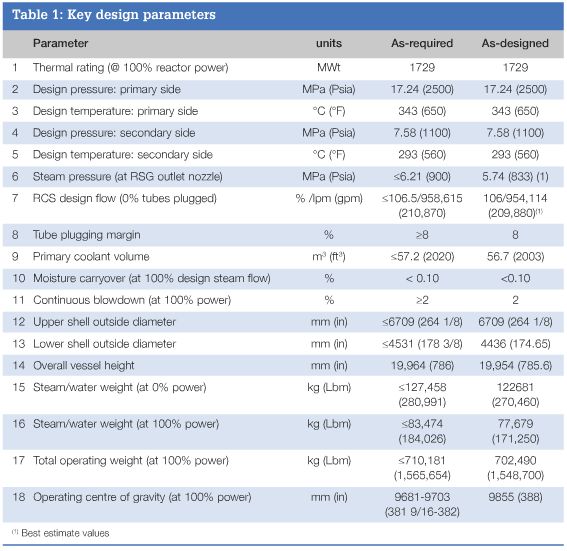
In order to meet all these objectives, the specification for design and fabrication of the SONGS RSGs imposed several requirements and limitations on the RSG design. These requirements and limitations for the key RSG parameters are listed in Table 1 and are compared to the values oi these parameters as-designed by MHI. This comparison clearly shows that the MHl design satisfied all specified requirements.
However. imposing the requirements listed in Table 1 did not mean that the RSGs were intended to be merely OSG duplicates. The SONGS RSGs were intended to include all possible improvements introduced by the industry into the steam generator design and fabrication processes based on the US industry operating experience with all PWR plants, inside and outside oi the USA.
Therefore, the SONGS specification also incorporated design and fabrication requirements derived from the SONGS operating experience with its OSGs. and the industry experience with the plants with both the OSGs and RSGs installed, including those supplied by MHI. These requirements were aimed at addressing these experiences and overall improving longevity, reliability, performance and maintainability of the steam generators. During RSG fabrication. strict quality controls were in effect at MHI to ensure as best as possible execution of the improved design and fabrication processes. All these requirements were imposed with the following goals in mind:
- To minimize wear of the steam generator tubes
- To eliminate susceptibility of the steam generator tubes to inter-granular attack (IGA) and primary water stress corrosion cracking (PWSCC)
- To provide tube-to\~tubesheet joints with proper strength, leak resistance and corrosion resistance
- To minimize general corrosion within the steam generators
- To eliminate susceptibility to thermal stratification in the feedwater inlet piping to the feedwater ring
- To eliminate potential for feedwater ring water hammer
- To maintain operating characteristics the same as that of the OSGs in terms of water level stability and controllability
- To optimize the materials of construction for the intended applications.
Design and fabrication
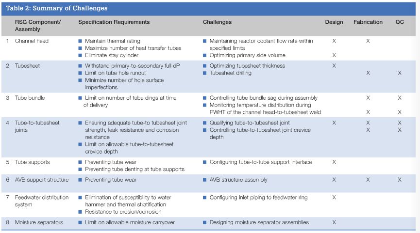
Including all these requirements and improvements in the RSG design without affecting their form, fit and function and their ability to be installed under the 50.59 rule. and satisfying the design requirements without exceeding imposed limitations presented many challenges for the Edison and MHI project teams. Table 2 summarizes the challenges which both teams faced over the design and fabrication cycle of the SONGS RSGs. The table lists the RSG components/assemblies for which meeting the specification requirements was particularly challenging in the areas of design, fabrication and/or quality control, the reason for which it was challenging and the area of the challenge. Below it is described how these challenges were addressed by the Edison and MHl project teams in order to obtain a satisfactory outcome.
Channel head
The RSG had to have the same thermal rating as the OSG, the number oi heat transfer tubes had to be maximized, the stay cylinder supporting the tubesheet had to be eliminated and the channel head had to have a. flat bottom. On the other hand, limitations were imposed on the maximum allowable reactor coolant flow rate to prevent the potential for fuel pin fretting and on a relative increase of the primary side volume to prevent exceeding containment allowable flooding levels.
These requirements presented two unique design and fabrication challenges. First, elimination of the stay cylinder allowed for installation of more tubes than there were in the OSG, but having more tubes was leading to higher reactor coolant flow rates. Second, having more tubes and no stay cylinder was leading to primary side volume increase. The first challenge was addressed by performing extensive computer modeling and 1 :5.2 scale model testing of the RSG primary side, which resulted in incorporation of a carefully-sized reactor coolant flow limiting orifice in the RSG hot leg. The flow orifice had to limit the flow rate somewhat, but not to the degree to which it might affect the reactor core thermal- hydraulics. The second challenge was addressed by reducing the volume of the channel head by lowering the tubesheet while still maintaining the channel head vertical clearance sufficiently to perform tube inspections and maintenance.
Tubesheet
The tubesheet had to be designed such that it could withstand the differential pressure resulting from the primary side being at the design pressure and the secondary side at atmospheric pressure, without excessive deformation. To meet this objective, the tubesheet had to be made thicker than in the OSG, as it was supported only by a flat structural divider plate in lieu of the stay cylinder. Also, the tubesheet had to be clad with Alloy 690 equivalent to provide a surface suitable for welding the heat transfer tubes made from Alloy 690. In addition. the tubesheet had to be fabricated with a very tight tolerance on tube hole runout, and with a minimal number of tube hole surface imperfections (for example, tool marks) to meet the requirements for tube-to-tubesheet joints.
A. thicker tubesheet clad with a very hard material, along with these fabrication requirements. presented a unique challenge for tubesheet drilling and quality control. This challenge was addressed starting with the use of the BTA drilling technique, through extensive mockup qualification testing and extensive quality control, and ending with utilizing modified drill bits having much better performance characteristics.
Tube bundle
The RSG tube bundle had to be fabricated such that the number of tube dings was minimized, and remained within the specified limit.
Considering the size and weight of the SONGS RSG tube bundles, this requirement presented two unique fabrication challenges.
The first challenge was tube bundle assembly when dings could be generated as a. result of the bundle sagging considerably. The second challenge was during post-weld heat treatment (PWI-IT) of the channel head- to-tubesheet weld when dings could he generated by bowing of the RSG vessel due to its uneven thermal expansion as a result of temperature stratification within the vessel.
The first challenge was addressed by customizing the assembly process, analytically determining the maximum allowable sag and monitoring the sag throughout the assembly process. The second challenge was addressed by analytically determining the maximum shell distortion and 1:1 scale model mockup testing to empirically determine the magnitude of shell distortion necessary to result in tube clinging.
Tube-to-tubesheet joints
The tube-to-tubesheet joints had to be designed such that they had adequate strength, leakage resistance and corrosion resistance. and that the tube-to-tubesheet crevice depth was kept within the specified limits. The single biggest challenge here was to devise and implement a competent joint qualification process. To address this challenge. an extensive and in-depth joint qualification program was developed, comprising both analytical and empirical elements, and was meticulously implemented in the MHI R&D centre, and properly documented.
Tube supports
The tube supports had to be designed such that the potential for tube wear due to flow- induced vibration was minimized, and the potential for tube denting at tube supports due to corrosion product deposition was eliminated. To achieve this objective, seven tube support plates made from Type 405 ferritic stainless steel with broached, trefoil tube holes were installed in each RSG. The tube support plates were designed with a flat-land tube-to-tube support plate contact geometry to reduce the tube\~to-tube support plate contact and crevice areas, while providing for a maximum steam/water flow in the open areas adjacent to the tube.
AVB support structure
The term 'AVB structure' describes tube supports in the tube bundle U-bend region. The AVB structure had to be designed such that the potential for tube wear due to flow induced vibration was minimized.
To achieve this objective. six sets of V- shaped AVBs made from Type 405 ferritic stainless steel, providing up to 12 support points per tube bend. were installed in the U bend region to provide support in the region where the tubes are most susceptible to degradation due to wear from flow-induced vibration. The single major challenge here was control of the AVB thickness and flatness, and tube-to-AVB gap size. This challenge was addressed by customizing the fabrication and assembly processes and implementing strict quality control in various stages of AVB fabrication and AVB structure assembly.
Feedwater distribution system
The feedwater distribution system consisted of the feedwater distribution ring and the inlet piping to the feedwater ring internal to the RSG. The feedwater distribution system had to be designed such that it was not susceptible to water hammer, the inlet piping had to be configured such that no thermal stratification occurred in this piping, and the inlet piping had to be especially resistant to erosion/corrosion. To address these requirements, the feedwater spray nozzles were mounted on the top of the feedwater ring to prevent it from draining. thus eliminating the potential for water hammer on steam generator water level decrease. The design of the inlet piping included a vented goose-neck extending above the elevation of the feedwater spray nozzles. This feature eliminated thermal stratification in the RSG feedwater nozzle and the inlet piping to the feedwater ring, and prevented the feedwater ring from draining on loss of main feedwater flow, thus also eliminating the potential for water hammer. The feedwater ring was fabricated from Cr-Mo alloy steel with the tee and elbows made from Alloy 690 TT. which provided excellent resistance to erosion/corrosion.
Moisture separators
The moisture separators had to be designed such as to provide the first stage of moisture separation adequate to limit the moisture carry-over in the steam leaving the RSG to no more than 0.1% by weight. For this purpose, MHI had to come up with a brand-new separator size and separator assembly configuration. In order to verify that the new design could meet this requirement, and to optimize the size of the individual separators and their number. MHI utilized the results of an extensive R&D programme conducted to develop the design of moisture separators for its smaller steam generators.
Results
Even though all design and fabrication challenges were addressed during manufacturing, it was not known if the as- designed and fabricated RSGs would eventually perform as specified. To verify this, the RSGs were functionally tested after installation in the plant after unit re-start from the replacement outage. The following essential operating parameters were verified through functional tests.
Heat transfer (steam pressure)
As-designed, the RSGs operating at full (100%) reactor rated power with the reactor coolant temperature at the design point were expected to generate steam whose pressure was to be no less than 816 psia (and no greater than 900 psia) at the steam outlet nozzle. As-tested, one RSG generated steam at approximately 831 psia (5.73 MIPa) and the other one at approximately 837 psia.
Water level stability
As-designed, in the RSGs operating at any power level between 0 and 100% reactor rated power, including ramp power level changes of up to +/-15% per hour, the maximum amplitude of the water level fluctuations was expected not to exceed +/- 1% of the narrow range span The test was performed in a form of simulator runs using the plant long-term cooling (LTC) model, as the 15% per hour reactor power changes could not be imposed on the plant during normal startup, shutdown, or power operation. The simulator nuns have shown that the amplitude of water level fluctuations was less than 1% under all specified transient conditions.
Moisture carryover
As-designed, the RSGs operating at full (100%) reactor rated power were expected to generate steam with moisture content less than 0.1% by weight As-tested. one RSG generated steam with moisture content of approximately 0.003796 and the other one with approximately 0.004296.
Reactor coolant flow rate
As-designed. with the RSGs operating at full (100%) reactor rated power with reactor coolant temperature at a design point, the 'as-measured' reactor coolant flow rate was expected not to exceed 106.5% of the original volumetric design flow rate. As-tested. the reactor coolant flow rate was 104.35% of the original design flow rate.
Primary-to-secondary leakage
As-designed, the RSGs were not supposed to exhibit a detectable primary-to-secondary leakage with the primary side at 2250 psia, and the secondary side at the normal operating pressure and temperature. As-tested, a primary-to-secondary leakage of less than 1 gallon per day (3.87 litres/day) was reported when the plant stabilized at full (100%) reactor rated power.
Blowdown capacity
As-designed, with the RSGs operating at full (100%) reactor rated power with reactor coolant temperature at the design point, the continuous blowdown capacity with the RSG installed was expected to be no less than that with the OSGs installed. As-tested, it was verified that with the RSGs installed the same blowdown flow rate could be attained as with the OSGs installed.
Authors:
Boguslaw Olech, P.E., Southern California Edison Company, 14300 Mesa Fld., San Clemente, CA 92674, USA, Email: bob.o%7Cech@sce.com.
Tomoyuki lnoue, Mitsubishi Heavy Industries Ltd. (MHI), 1-1 Wadasaki-cho 1-Chome, HyogoKu, Kobe, Japan 652 8585, Email: tomoyuki_inoue@mhi.co.jp.
The authors wish to acknowledge all Edison and MHI personnel involved in the SONGS steam generator replacement project for their efforts to make this project a success.
This article was based on a paper published at ICAPP 2011, 2-5 May 2011, Nice, France, paper 11330
- Image 1:
- Image 2:
- Image 3:
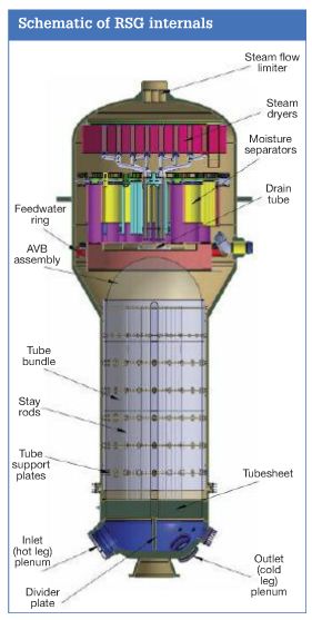
- RSG Internals:
- Table 1:
- Table 2: